Basic behavior of wiring elements and electrical state behavior.
Wiring Basics[ | ]
How power is transmitted[ | ]
The source of all power is a power source. If there is a conductive path from a power source to an object that reacts to power, then that object will be turned on. This only happens in self tests and robberies, in build mode power does not propagate and most objects will appear off.
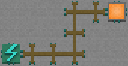
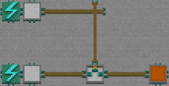
In this image you can see that wires are conductive so power can pass from the source, through the wires, to the indicator light and thus turn it on. Orange indicator lights are also conductive. This means you can use them as a path for the electricity to take, and they will also light up when powered:
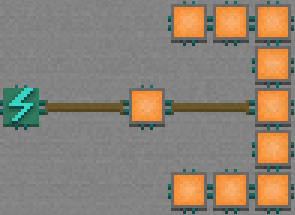
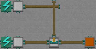
As you can see, the lights pass power through. It's important to note that there are some tiles that are not completely conductive, but rather only let power pass through one way, an example of this is horizontal wire:
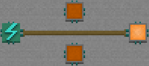
These wires do not pass power up or down, just horizontally. The lights are not powered because they are not receiving power. Components do not "draw" or "pull" power out of tiles, the power must be fed into them.
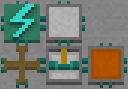
Next to note is that some tiles are not conductive at all, but still react to power:
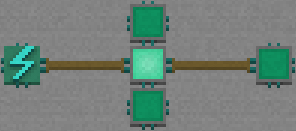
Turquoise indicator lights are not conductive. If power is fed into them they will turn on, but they will not pass power to surrounding tiles. Here you can see that the first light is directly powered by the wire. Power cannot get through this light to the wire behind or lights above and below, so no more are powered.
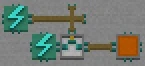
Switches generally change between being conductive and not conductive, for example:
![]()
The switch is in its up state, in which it is not conductive. Power can not get through to activate the light. When we press it however:
![]()
It goes into its down state, in which it is now conductive. Thus, power can get through and to the light.
Some tiles are conductive, and others are not. Here are a few of the traps you are likely to be using:
![]() Trap doors are not conductive.
Trap doors are not conductive.
![]() Neither are powered doors.
Neither are powered doors.
![]() Electric floors, however, are conductive.
Electric floors, however, are conductive.
All electricity state changes appear to occur immediately, there is no "propagation delay" [1] like in Minecraft, however some more complicated mechanism however do make use of the fact wiring is calculated in "sub-steps" in which there is a delay.
Gates and logic[ | ]
Voltage Triggered Switches and Voltage Triggered Inverted Switches are important components for most wiring beyond the very basics.
![]() A Voltage Triggered Switch in its default, unpowered, state. It does not conduct in this state.
A Voltage Triggered Switch in its default, unpowered, state. It does not conduct in this state.
![]() A Voltage Inverted Triggered Switch in its default, unpowered, state. It conducts horizontally in this state.
A Voltage Inverted Triggered Switch in its default, unpowered, state. It conducts horizontally in this state.
These tiles look and act similar, but are inverted from each other. When either is powered from above the conductive "bar" on the visual sprite will move downwards.
![]() On the Voltage Triggered Switch this means that the bar moves into a position where it appears to connect the two sides, and hence now conducts horizontally.
On the Voltage Triggered Switch this means that the bar moves into a position where it appears to connect the two sides, and hence now conducts horizontally.
![]() On the Voltage Triggered Inverted Switch this means that the bar moves down and no longer connects the two sides, and hence now does not conduct.
On the Voltage Triggered Inverted Switch this means that the bar moves down and no longer connects the two sides, and hence now does not conduct.
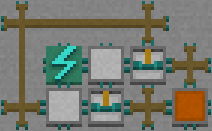
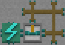
With these behaviours "Logic gates" can be made:
This is an "And" gate. For the light to be on, both switches have to be pressed down. The upper switch lets power flow through to the top of the Voltage Triggered Switch, and thus pushes the bar down. The second switch lets power flow through this switch horizontally.
If only the the upper switch was pressed then the bar would be down, but there would be no power to get through to the light. If only the lower switch was pressed, then the power could not get through the Voltage Triggered Switch as it would be in its non-conductive state.
This next example looks almost identical, but has a Voltage Triggered Inverted Switch instead of a normal Voltage Triggered switch:
If the bottom switch is pressed, then power can get through to the light. However if the upper switch is pressed, it powers the Voltage Triggered Inverted Switch which will then cut off power to the light. For the light to be powered the bottom switch has to be pressed and the upper one has to be unpressed.
Below are descriptions of all electrical components, and then a table of logic gates.
Wiring Components[ | ]
- Wire - normal wire connects all four edges to let power through, vertical wire connects only the top and bottom, horizontal wire connects only the left and right.
- Wired Wooden Wall - acts like wire, but blocks movement like a wooden wall.
- Pressure Toggle Switch - changes state from conductive to non conductive and vice versa when stepped on by robbers or animals.
- Sticking Pressure Switch - initially non conductive, changes to conductive when stepped on and cannot be toggled back off.
- Rotary Toggle Switch - acts like vertical/horizontal wire and toggles between them when stepped on. Initially vertical power is connected.
- Wire Bridge - connects power vertically and horizontally, but does not let them interfere.
- Voltage Triggered Switch - conducts horizontally when power is applied to the top, does not conduct when there is no power applied.
- Voltage Triggered Inverted Switch - conducts horizontally when there is NO power applied to the top, does not conduct when there is power applied.
- Power Source - applies power to adjacent tiles.
- Indicator Light - Green - lights up when powered, but does not conduct power (acts like Powered Door or Trap Door).
- Indicator Light - Red - lights up when powered, and conducts power (acts like Electric Floor).
- Panic Button - only button that can be activated by family. Acts like a Sticky Pressure Switch. Cannot be pressed by pets or player.
- Trap Door - Safe (closed) when powered. Deadly when unpowered. Does not conduct electricity.
- Powered Door - Acts as a wall when powered. Open when unpowered. Does not conduct electricity.
- Electric Floor - Deadly when powered. Safe when unpowered. Conducts electricity.
Logic Gate Examples[ | ]
| Description | Image | Truth Table | ||
| OR If either button is pressed, the light activates. |
 |
A | B | A+B |
| 1 | 1 | 1 | ||
| 1 | 0 | 1 | ||
| 0 | 1 | 1 | ||
| 0 | 0 | 0 | ||
| AND If both buttons are pressed, the light activates. |
 |
A | B | A.B |
| 1 | 1 | 1 | ||
| 1 | 0 | 0 | ||
| 0 | 1 | 0 | ||
| 0 | 0 | 0 | ||
| NOT If button is not pressed, the light activates. |
 |
A | A̅ | |
| 1 | 0 | |||
| 0 | 1 | |||
| XOR If only one button is pressed, the light activates. |
 |
A | B | A⊕B |
| 1 | 1 | 0 | ||
| 1 | 0 | 1 | ||
| 0 | 1 | 1 | ||
| 0 | 0 | 0 | ||
Substeps[ | ]
You'll probably eventually make something like this and wonder what happens:
The power should at first get through, letting it up and around to the top of the switch. This however turns the switch on, which stops power getting through. Now that no power is getting through though the switch should become unpowered and let power through again; it should get stuck in a loop!
If you make it though you'll see that it doesn't rapidly change back and forth as fast as the game can handle, or even just when you take a step, it "settles" into a state that looks exactly like it does in the picture. To understand why we first need to understand substeps.
A lot of the following examples will be created in castledraft, the map editor, as it allows showing which wires are on and which are off.
For the game to figure out the final state of electronics, it goes through many "substeps". This simulation happens every single time a robber makes a move or uses a tool.
In a substep, first, power propagates through anything conductive that it can. Then at the start of the next substep, voltage triggered (inverted) switches are triggered according to whether or not they were receiving power at the end of the last turn. The game keeps running through substeps until wiring in the whole house repeats a "state" and one substep exactly matches another.
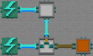
Lets say we make something like this:

When we step onto the switch, power will immediately get through the conductive switch and wire, but won't yet trigger the voltage triggered inverted switch (VTIS).
It will take until the start of the next substep for the switch to update according to whether or not it is receiving power from above:
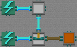
Once this happens, power can immediately get through on this same (second) substep:
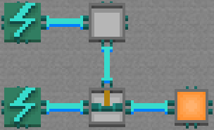
And the light is powered. On the third substep the game sees that everything has stayed exactly the same, so stops the simulation at three substeps and gives the above state as the final state that you see.
Joshwithguitar put together a castledraft map to act as a visual guide to electronic substeps: http://castledraft.com/editor/2sP62y
Each row in the above example represents the substeps that the game goes through in order to determine the state of the different electronic configurations.
In the rows the leftmost circuit represents the initial state of a circuit before a pressure switch is turned on. The circuits to the right represent each cycle after the button is pressed until it repeats a state. The to the far right the final state as it will appear to the player.
Going back to the initial circuit though, what happens with this?:
This map shows the substeps that it will go through: http://castledraft.com/editor/oJviC2
By the third substep the game detects a repeated state, where everything is exactly the same as it was before, which means that it is going to loop. It doesn't need to go through any substeps after the third. The game simulates this loop again and finds the lowest seen state of each tile. This means their unpowered state. It then settles each tile individually down into their lowest seen state, and you end up with the circuit shown on the far left, which also happens to be what it looks like in build mode.
Even though it looks like power should be getting through, the game has forcefully decided that the wires and VTIS should be off, as that was the lowest state they were seen in during the loop.
Tips[ | ]
Power flows both ways along wires, so be careful when using multiple gates together. Although in this example it seems like the bottom light only lights up if both switches are powered, pressing the bottom button will also provide power to the voltage trigger switch, lighting up the light even though only one button is pressed. One solution to this problem of bi-directionality is to use a "diode" type circuit.
Related Topics[ | ]
- Advanced Electronics - such as bit-storage, pulses, counters, clocks, and how electronics cycles work
- Traps Guide - applied wiring for creative and interesting traps